
Tu carrito está vacío

- TURNKEY SOLUTIONS
- TRANSMISSION
- RADIO
- PRO AUDIO
- PODCAST
- VIDEO
- RESOURCES
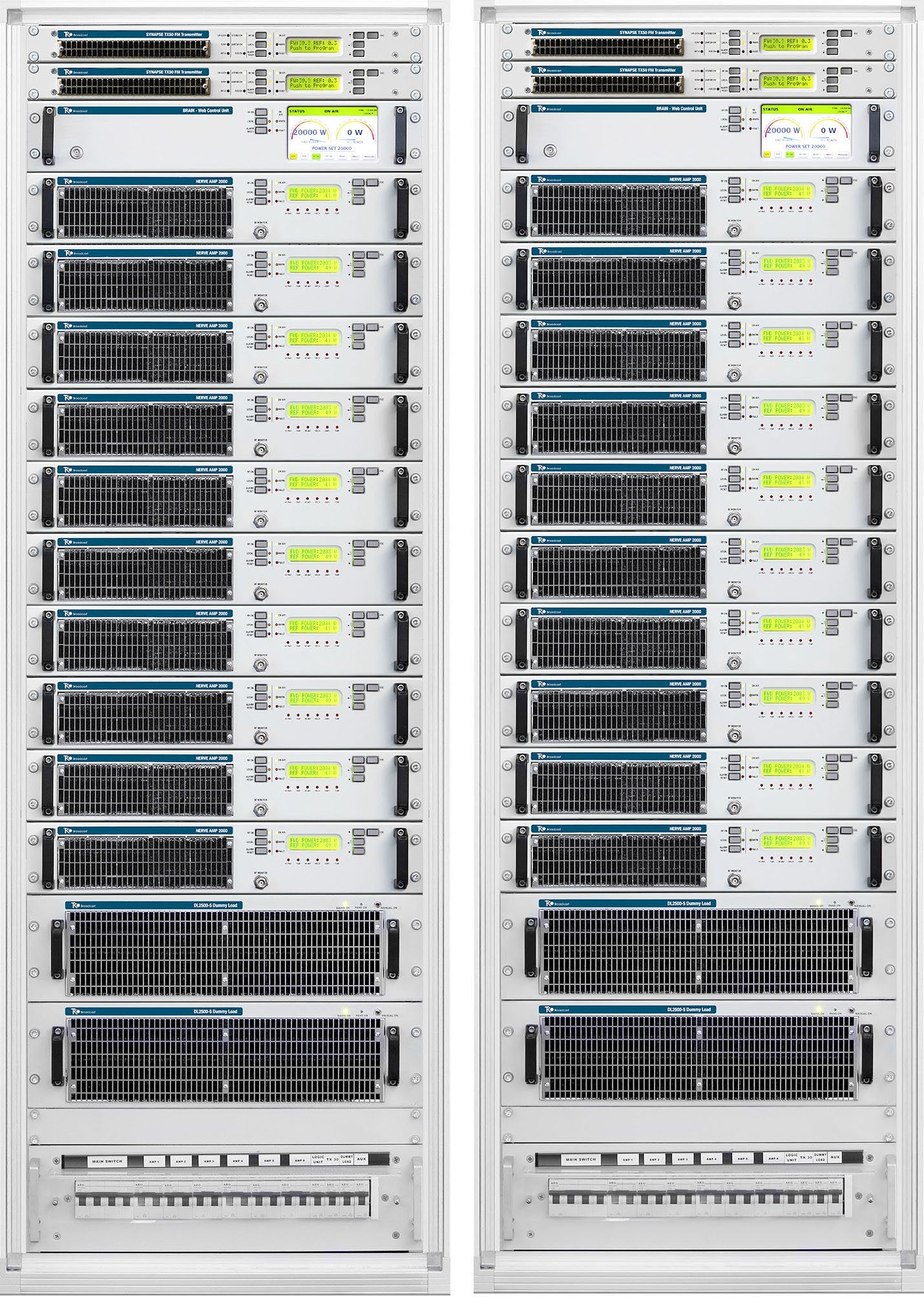
Full range of power available Modular Combined in SMP: Superior Modular Philosophy.
Series Standard and HOT PLUG-IN versions available; Analog and Digital Ready for HD Radio and DRM High Power FM The top sale to Governamental, Commercial and Comunity Radio Stations Air cooled Frequency Modulation 88 to 108 MHz.
CELL Series High Efficiency
• LDMOS Amplifiers 1,1kW or 2,2kW
• Hot Plug-in Power Supply
• Up to 75% Overal Efficiency
• PLANAR LDMOS
• 65:1 VSWR Tollerant
• Fully RF and Power
• Supply
• Redundant TXM SMP
Superior Modular Philofophy When developing SMP Technology, Superior Modular Philosophy, the main target was: Always on Air, Less than 15 kg of modules-weight, Easy maintenance, Low consumption and High Efficiency
REVOLUTIONARY MODULAR COMBINER BROKEN THE PORT NUMBER LIMITS.
Ultra Compact Design.
• Low power to high power direct stepping.
• Low loss.
• Non Hierarchy Arbitrary odd and even port number.
• Ground referred balancing loads.
• Extremely high isolation value: more than 26dB.
• Up to 10 input way for 20 kW Output Power.
• Ultra-wideband, exceeds more stringent specifications.
• Phase stable.
• Best in class low loss performance: less than 0.1dB
• More than 12 dB of additive harmonic filtering.
• Low Cost vs Power ratio.
The Combining system is composed by the COMBINER itsef, the ISOLATED SPLITTER 2-10 way and the UNBALANCED POWER LOAD 2-10 way
SWAP SERIES BLOCK DIAGRAM
Fully MODULAR and Extreme Redundancy
Every part of the transmitter is Redundant, Amplifiers, Exciter, Dummy load. >The maximum redundancy is given by the indipendency of the work of the single amplifier from the others or from the central control logic. The transmitter can work even without it.
The CORTEX SMP© Superior Modular Philosophy is a family based on a very compact Amplifier Module.
It combines form 2 to 10 Low Power RF amplifiers to create a High Power FM Broadcast Transmitter.
Thanks of the size, 2 HE, power levels 2,2 kW, it is the more redundant Modular FM Transmitter of the market.
The CELL RF Amplifier has 2,2kW output power with High Efficiency Planar LDMOS Technology.
The modular architecture is completed with:
• High Efficiency Solid State FM Amplifiers
• Special combiners
• FM exciters and control logics
• The FM exciter can be Analogue or DDS
• Both with integrated AES/EBU interface
• FM Stereo Transmitter/Exciter
• Has built in Stereo Generator
SMP unique TEKO Radio Equipment Architecture is every modular and able to grow in power (scalar) and the robustness.
SMP, based on combine low power amplifiers, gives the maximum output power in case of fault of one amplifier.
SMP is the Radio Station Equipment more Robust of the broadcast chain.
To better understand the benefits of it’s philosophy, let us explain how it works a Radio FM Broadcast System.
How an FM Radio Broadcast System is composed
I’s composed by many parts like:
Transmitter
Antenna
Radio Links
the Mains Electric Supply
;etc.
…..but everybody agrees the king is the FM Transmitter.
FM Transmitter Structure
It is mainly composed of two parts:
The FM Exciter, even known as FM Modulator.
The output RF Amplifier.
When it’s necessary to have High Power Transmitters this are obtained by combining two or more RF Amplifiers.
So, the complete FM Transmitter chain is build as follows:
Starting by an FM Exciter and then..
This low power FM Signal is amplified by several RF Amplifiers and then...
This combination creates a Low, Medium or High Power FM Transmission system.
RF Amplifier
The LDMOS, the heart of any RF amplifier, is the active component that produce the amplification.
The LDMOS amplifiers the Low Output Power FM Exciter, to the high Power at the output of the Transmitter.
The LDMOS has the ability to handle high RF Power levels with a big capacity of Heat Dissipation.
On FM Radio application the maximum power handle by the LDMOS with the modern technology about 1kW or 1,5kW.
To reach higher power levels is necessary to combine them in to reach higher power levels.
The most common LDMOS devices used on the Broadcast Industry at the moment are:
• BLF188.
• BLF189. MRF1K25. MRF1K5
• and MRF1K8.
The strategy used by the Producers is to combine a number LDMOS in a single Medium Power RF Amplifier.
The RF Amplifiers output power in a range between 1kW and 6kW.
The amplifier is obtained by the combination of a variable number (between 2 and 6) LDMOS devices.
With this number of LDMOS it’s obtained output powers between 2 and 6 kilowatts.
High Power FM Transmitter
It’s built combining two or more Medium Power RF.
A High Power FM transmitter is obtained by the combination of a variable number, between 2 and 10.
To do this, the constructors choose between four philosophies:
• Use only one high power FM Amplifier Module.
• Combine High Power Amplifiers Modules.
• Combine Low Power Amplifiers Modules “only RF” type, it means, an RF Module without Power Supply, Fans and Control Logic.
• Combine Low Power Stand Alone Amplifiers Modules (this is the option adopted on CORTEX).
WHAT A BROADCASTER NEEDS FROM AN FM TRANSMITTER
They are few essential things, the transmitter must be:
• Always on Air: this is the main thing, nothing is more important, It must me reliable.
• Easy maintenance.
• Easy to transport and handle by one person, it avoids the needing to go two or more technicians to make maintenance
• The optimal wight is modules with less than 15 kg (35 lbs) weight,
• Low Energy consumption.
CORTEX SMP© Superior Modular Philosophy
To full meet the Broadcaster needs, we create a modular structure with an RF Amplifier Module, obsessively optimized for best results.
Big broadcast systems benefits of this optimization.
SMP Superior Modular Philosophy is the synthesis of robustness easy maintenance and low energy consumption.
CELL RF Amplifier and Pulse Amplifier
To meets all the needing of the broadcaster, the base module CELL Amplifier was extremely optimized by means of maximize: · Efficiency, · high reliability · Electrical performance · Networking · Easy the maintenance and minimize: · weight · power · consumption · heat produced on the site In this way the entire system benefit of it A key to make easy the maintenance is to test and repair the amplifier module in Laboratory without special tools required. The module can be repair even on the site! To allow this the CELL Amplifier are complete functioning with it own power supply ventilation, control logic and output filter. At the opposite of the standard plug-in transmitters, the Amplifier Module facilities the maintenance and the test: no need of special tools each module can be connected and installed or tested as a single amplifier. a single CELL Amplifier can be put on air as back-up of a bigger transmitter. Shock and vibration during the transport process can compromise the result of an installation. Optimizing the CELL Amplifier dimension and weight allows a small and smart package Small weight and dimensions help to meet the most demanding transport conditions for: Hermetic temperature control vibration and Shock Isolation handling light packs aid the health of the operators.
• Last generation 1400 W LDMOS, VSWR > 65:1 @ all Phase Angles, designed for enhanced ruggedness ISM applications and plasma generators.
• Integrated AC Mains filtering.
• Integrated lightning protection.
Hardware and Software Protections:
Over and Under Voltage DC RF and Power Supply Temperature RF Coaxial Output Open or Short Circuit Able of a long working time on Short/Open loads at all phase angles without any damage. Delayed energized of the system after Mains Power Blackout prevents against peaks and high variation voltages typical of this events.
• •Each module is equipped with a logic controller that allows full control by a local operator.
• All transmitter and amplifier parameters required for diagnostics can be retrieved: Locally Remotely Via standard (IP) protocol With standard software (web browser, SNMP).
KEY FACTS
Combining System
• Compact and well isolated up to twelve way 20 kW PC Power Combiner.
• Ultra-broadband, phase stable, low loss and showing more than 20 dB of additive harmonic filtering.
• FM transmitters featuring only 800 mm rack depth and up to 40 kW FM in a single 19” rack.
• Digital TV Transmitters up to 8 KW Wide Band Doherty (WBD) output power in a single 19” rack.
WEB/SNMP Telemetry and Remote Control
• Full Local or Remote control by by logon username and password.
• Remote control with Smartphones or Tablet.
• Host Logic and tele-measurement (TM, TC & TA).
• Remote control and monitoring via SNMP and/or WEB interface.
• With logbook or log file to record error or alarm message.
• Display of forward/reflection power value and reflection high alarm.
Human Interface
• Multilingual user guidance.
• High Definition, high contrast LCD display.
• Quick set of thresholds for protections level.
This set is based on assignment of three “flavors” or PERSONALITIES:
• Conservative (primary target = protect itself).
• Standard (balanced).
• Aggressive (primary target = transmission without interruptions).
• N+1 and Backups systems
• Conventional standby systems such as: exciter standby, (n+1) Transmitter standby, passive standby and active output stage standby can be implemented.
• No additional control units are needed for the exciter standby and the active amplifier standby.
80kW FM Transmitter Series Standard and HOT PLUG-IN versions
• Audio Source Selection
• Several Transmitter Ranges
• Based Control
• Analogue and Digital Ready for HD Radio and DRM
• Based on CELL Series High Efficiency RF Amplifier Module
• CELL LDMOS Amplifiers 1,1kW or 2,2kW
• Hot Plug-in Power Supply
• Up to 75% Overal Efficiency
• PLANAR LDMOS
• 65:1 VSWR Tollerant
• Fully RF and Power
• Supply
• Redundant TXM SMP
REVOLUTIONARY MODULAR COMBINER
BROKEN THE PORT NUMBER LIMITS.
• Ultra Compact Design.
• Low power to high power direct stepping.
• Low loss.
• Non Hierarchy Arbitrary odd and even port number.
• Ground referred balancing loads.
• Extremely high isolation value: more than 26dB.
• Up to 10 input way for 20 kW Output Power.
• Ultra-wideband, exceeds more stringent specifications.
• Phase stable.
• Best in class low loss performance: less than 0.1dB
• More than 12 dB of additive harmonic filtering.
• Low Cost vs Power ratio.
The Combining system is composed by the COMBINER itself, the ISOLATED SPLITTER 2-10 way and the UNBALANCED POWER LOAD 2-10
|
RVR, Nautel, Gates, GatesAir, Elenos, ETG1000, ETG5000, ETG2000, RVR TX1000, Nautel NX, Broadcast Electronics BE, BE, FM-5C
|